Calibration of a diffraction setup using the Command Line Interface (CLI)#
The files needed for this cookbook can be downloaded on: http://www.silx.org/pub/pyFAI/cookbook/calibration/ You can download them to practice:
$ mkdir calibration
$ cd calibration
$ wget http://www.silx.org/pub/pyFAI/cookbook/calibration/LaB6_29.4keV.tif
$ wget http://www.silx.org/pub/pyFAI/cookbook/calibration/F_K4320T_Cam43_30012013_distorsion.spline
$ ls
F_K4320T_Cam43_30012013_distorsion.spline  LaB6_29.4keV.tif
Review your calibration image#
As viewer, try fabio_viewer from the FabIO package
$ fabio_viewer LaB6_29.4keV.tif
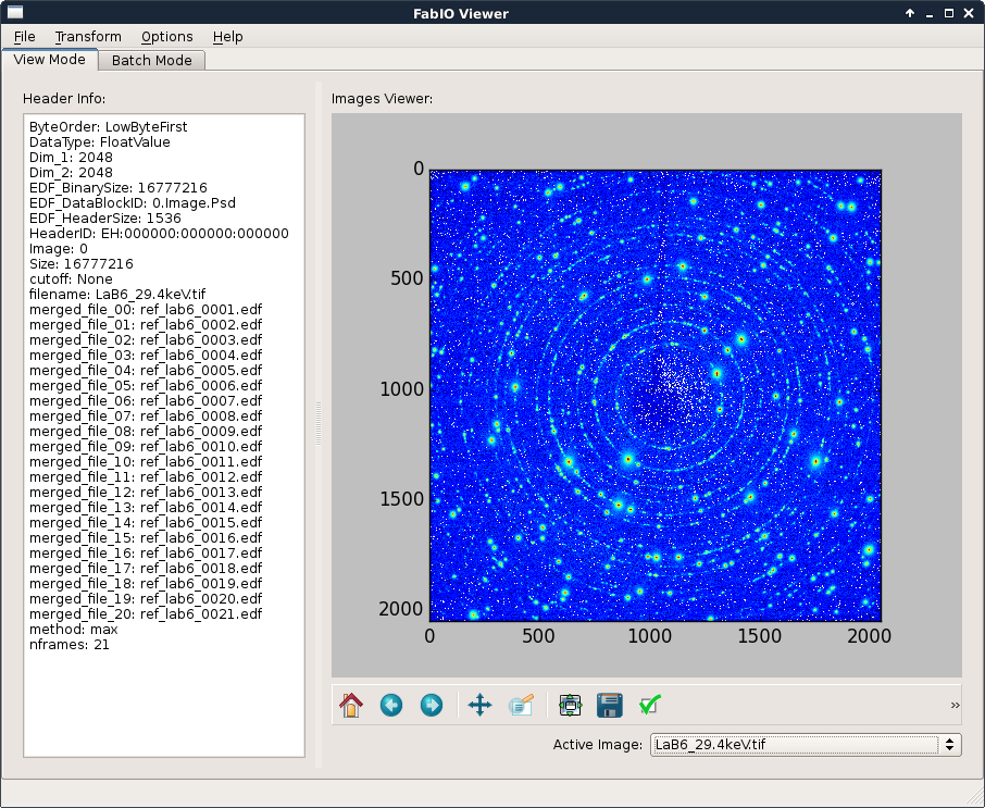
You may need to pre-process your data, pyFAI-average is a tool to perform pixel-wise transformation. In this example, the image file was obtained using a “max filter” over 20 frames with pyFAI-average:
$ pyFAI-average -m max -F tif -o LaB6_29.4keV.tif ref_lab6_00??.edf
Get all additional data#
calibrant used: LaB6 according to the name of the file
the energy or the wavelength, 29.4keV according to the name of the file
detector geometry: there is a spline file along with the file
masks, dark, flat … are not going to be used to keep things simple.
Start pyFAI-calib#
Use the man page (or –help) to see all options, or go to the Application manuals section.
Here we just provide the energy, the detector disortion file and the calibrant options in addition to the image file.
$ pyFAI-calib -e 29.4 -s F_K4320T_Cam43_30012013_distorsion.spline -c LaB6 LaB6_29.4keV.tif
FixedParameters(['wavelength'])
ERROR:pyFAI.peak_picker:ControlPoint.load: No such file LaB6_29.4keV.npt
INFO:pyFAI.massif:Image size is (2048, 2048)
INFO:pyFAI.massif:Binning size is [2, 2]
INFO:pyFAI.massif:Labeling found 7272 massifs.
INFO:pyFAI.massif:Labeling found 7272 massifs.
INFO:root:Please select rings on the diffraction image. In parenthesis, some modified shortcuts for single button mouse (Apple):
 * Right-click (click+n):         try an auto find for a ring
 * Right-click + Ctrl (click+b):  create new group with one point
 * Right-click + Shift (click+v): add one point to current group
 * Right-click + m (click+m):     find more points for current group
 * Center-click or (click+d):     erase current group
 * Center-click + 1 or (click+1): erase closest point from current group
Please press enter when you are happy with your selection
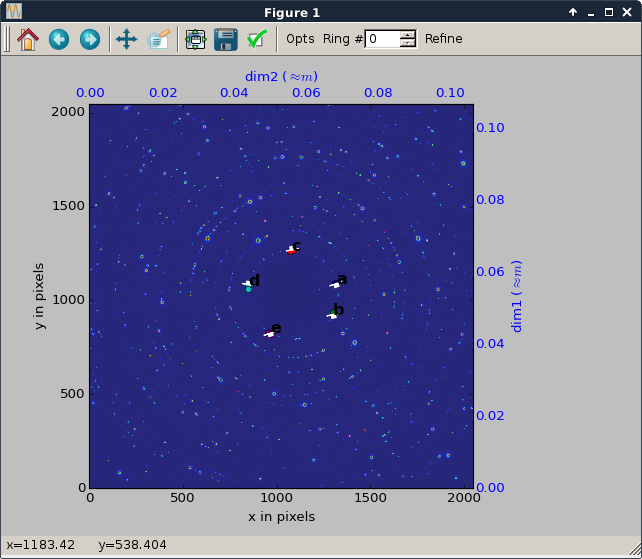
Pick peaks#
To perform the calibration one needs to create control points and assign them to rings.
Right click on a few (5) points in the inner-most ring which has the index number #0
Increase the counter on the top right to change the ring number and pick a few more points on the corresponding ring (again with right click).
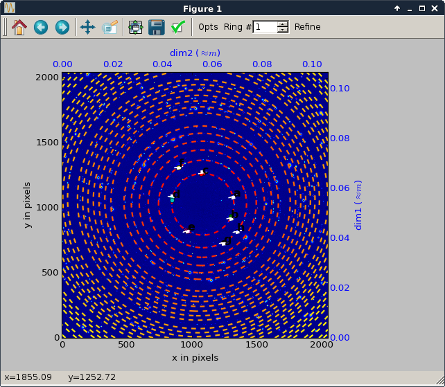
Review the group of peaks#
Press Enter in the terminal to do so… and check the ring assignment
Once done with all groups, the position of the expected rings is overlaid to the diffraction image. You may need to unzoom to view them !
Now fill in the ring number. Ring number starts at 0, like point-groups.
Point group # a (4 points)  (1315.9,1090.1)   [default=0] Ring#
Point group # b (5 points)  (1302.0, 926.0)   [default=0] Ring#
Point group # c (2 points)  (1085.3,1268.1)   [default=0] Ring#
Point group # d (2 points)  ( 850.1,1083.3)   [default=0] Ring#
Point group # e (5 points)  ( 965.1, 825.7)   [default=0] Ring#
Point group # f (4 points)  ( 898.2,1315.9)   [default=1] Ring#
Point group # g (2 points)  (1244.6, 733.6)   [default=1] Ring#
Point group # h (2 points)  (1350.1, 821.9)   [default=1] Ring#
Optimization terminated successfully.    (Exit mode 0)
Acquire some more control points#
Use recalib to extract a new set of control points, specify the number of rings, first a few of them then more
You may want to free/fix/bound some parameter then refine again
Fixed: wavelength
Modify parameters (or ? for help)?   recalib 6
[...]
Fixed: wavelength
Modify parameters (or ? for help)?   recalib 15
[...]
Fixed: wavelength
Modify parameters (or ? for help)?   recalib 25
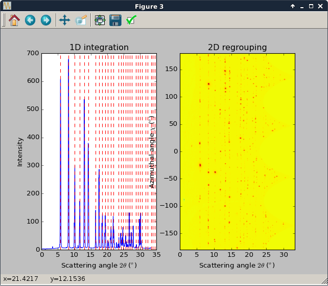
Visualize the integrated patterns#
integrate to view the integrated pattern
then extract a few extra rings …
the geometry is displayed on the screen, and saved automatically in the poni-file
Fixed: wavelength
Modify parameters (or ? for help)?   integrate
Quit#
Fixed: wavelength
Modify parameters (or ? for help)?   quit
$
ls
F_K4320T_Cam43_30012013_distorsion.spline  LaB6_29.4keV.npt   LaB6_29.4keV.tif
LaB6_29.4keV.azim                          LaB6_29.4keV.poni  LaB6_29.4keV.xy
All different geometries have been saved into the LaB6_29.4keV.poni file and can directly be used with pyFAI-integrate. All control points are saved into LaB6_29.4keV.npt.
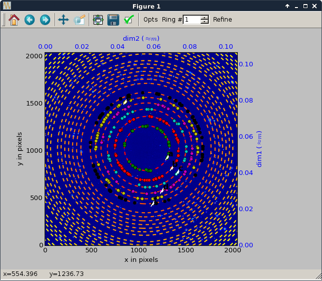
Final notes: In this case the calibration is far from being good and it is likely the distortion file applied is not the proper one according to many the waves on the 2D integration pattern. If one flips up-down the spline file prior to the calibration, the residual error is twice lower but the goes far beyond this cookbook. Here is the diffraction pattern from a properly calibrated setup:
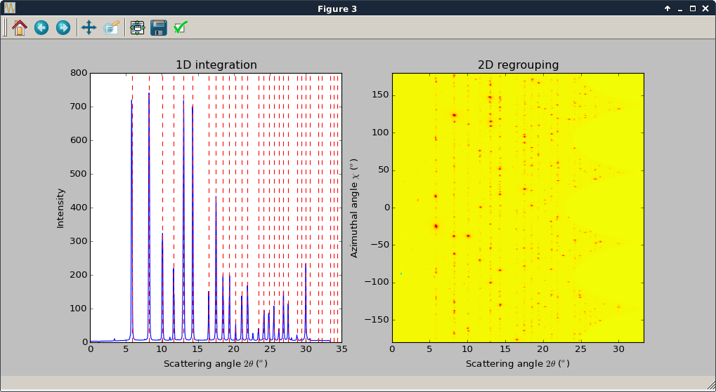
from pyFAI.spline import Spline
s = Spline("F_K4320T_Cam43_30012013_distorsion.spline")
ud = s.flipud()
ud.write("flipud.spline")